AGR’s Lead Geologist discusses the role of geomechanics during the production and injection drilling operations.
The relevance of geomechanics
Reservoir simulations are performed using industry standard software packages that utilise finite difference calculations of changes in key parameters (saturation, flow, pressure etc.) within and between cells at certain time steps. These calculations usually treat the rock properties such as porosity, and permeability as constant in any given cell throughout the simulation. Geomechanical models can allow some of these parameters to be changed in response to deformation imparted during the production / injection operations.
An important element of understanding the effects of geomechanics on a reservoir is the effective stress concept. This concept has a number of forms with varying degrees of complexity but at its simplest, the stresses acting on a rock at a given point in time and space can be defined as the total stress acting on that point (from gravitational and/or tectonic loading) minus the pore pressure. Therefore, changing the pore pressure during reservoir development will change the effective stress which in turn may lead to deformation and changes in other material properties such as porosity or permeability.
Rocks can deform in a variety of ways which are dependent on the material properties, the stress state during deformation and the rate of deformation. The largest distinction is between recoverable deformation (elastic behaviour) and non-recoverable deformation (viscous or plastic deformation). In very simplistic terms, most rocks will deform elastically at low stress levels or with small strains and viscous deformation occurs at higher stress levels or larger strains. In terms of timeframes relevant to geomechanics the two extremes are small scale, rapid and large changes in pore pressure and stress that can be induced during drilling or stimulation operations vs the much larger scale, longer timeframe changes in pore pressure and stress during tectonic deformation. Reservoir development effects relevant to simulation sit in-between these two extremes of scale with the potential for field scale changes over 10’s or even hundreds of years.
Key geomechanical material properties in simulations
The key material properties used in simulations that are potentially affected by geomechanics are compressibility, porosity and permeability. There is a further distinction between these values in rock matrix and open fractures. Matrix compressibility is the inverse of bulk modulus (Km) which is a key component used in the elasticity equations to relate stress and strain in the Earth under stable conditions. Km can be measured relatively accurately during hydrostatic loading experiments in the laboratory. At the field scale, the total bulk modulus (K) may vary due to a number of other factors such as variations in porosity and the presence of open fractures. During changes in reservoir pressure, bulk modulus, porosity and permeability can all vary due to the changes in the effective stress load borne by the rock system (matrix plus fractures).
Geomechanical processes during production or injection drilling
If we imagine a typical gas bearing sandstone reservoir undergoing depletion we can qualitatively assess the effects of that depletion on the rock system. As the depletion progresses, the effective stress increases. Initially, the matrix and any open fractures with deform elastically, matrix porosity will decrease by an amount controlled by the strength of the rock. This porosity reduction will probably also reduce the matrix compressibility. This effect is mirrored in any open fractures but the magnitude is more marked with large changes in fracture compressibility and porosity expected during early depletion. Matrix permeability may change (i.e. decrease) during early depletion but the effects are often minimal. Fracture permeability is a cubic function of fracture aperture (which also controls fracture porosity) so any open fractures may see a large drop in permeability during early depletion. This effect assumes that the fractures are primarily affected by stresses acting to close the fracture normal to its orientation. If shear stresses acting parallel to the fracture are also considered, these may act to slip the fracture and maintain or create new permeability pathways. So far in our example description, these strain effects are largely elastic (i.e. recoverable) in the matrix and a combination of elastic and plastic (i.e. non-recoverable) in the fractures. As depletion progresses further the effects on the matrix may become more marked with the potential for plastic deformation (compaction) occurring. This can lead to significant changes in porosity as seen in many depleted chalk reservoirs although the relationship to permeability is less obvious. In some cases the permeability is not reduced as much as expected. This could be due to slip on existing fractures or the creation of new shear fractures as the effective stresses exceed the shear strength of the rock. Some of these shearing events may be large enough to create earthquake events.
In addition to the potential for changes in the reservoir itself, there are also possible changes in the overburden. Even if the reservoir rock is strong and will only deform elastically during any planned depletion, weaker rocks and/or faults and fractures in the overburden may respond to the strains by deforming plastically. In extreme cases where there is significant reservoir compaction, this can lead to significant surface subsidence and earthquakes in the overburden (e.g. Groningen Field).
Enhanced oil recovery, steam flooding, water injection or CO2 disposal operations can not only induce similar changes to those described above but there is the added effect of thermal stresses affecting the near wellbore environment around injectors. Where cooling can occur around water or CO2 injectors, contractive strains will cause an increase in tensile stresses around the wells. This may lead to a local reduction in the tensile fracture gradient meaning fracturing of the formation (or the overburden) is more likely during continued injection. This effect is occasionally exploited during water injection to increase injection rates and conformance but it may lead to unwanted injection pathways if it is not properly controlled. Conversely, during steam injection, the compressive stresses may increase as well as the pore pressure leading to material failure from shear.
How to model geomechanical processes
The practicalities of implementing these changes in reservoir models can be addressed through coupled simulations. Initially, data should be interrogated to determine whether there are relationships that may warrant geomechanical modelling.
Some examples are:
- open fractures controlling mud loss intervals or PLT inflow points measured changes in reservoir porosity
- permeability in later wells vs earlier wells
- injection water with tracers shortcutting to producers via fractures.
Geomechanical simulators such as Visage, Elfen or Comsol utilise implicit or explicit finite element formulations where the stress, strain and geomechanical property changes in the reservoir are tracked as material properties and/or changes in the grid cell dimensions. Two way coupling allows for output from a predefined simulator timestep (temperature, saturation, pressure) to be used as input to a geomechanical simulation. After the geomechanical simulation, the reservoir compressibility, porosity and permeability properties can be updated either via simple correlations relating to the geomechanical model parameters or to more sophisticated constitutive material property models. The next reservoir simulation timestep is then performed using these updated properties and so on.
To sum it up
In summary, where the amount of depletion / pressurisation in a reservoir is low or the expected strains are small, it is unlikely that coupled geomechanical simulations are required. However, where the reservoir pressure changes are expected to be large or the reservoir +/- overburden may be particularly sensitive to the planned operations, coupled geomechanical modelling should be employed to investigate the potential effects and provide bounds on parameters such as production or injection rates and final pressures at abandonment.
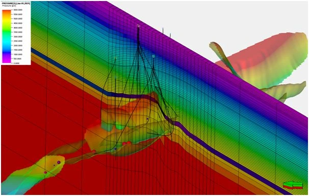
Modelled maximum depletion in a producing gas reservoir (psi). Larger cells with horizontal layers on the edges of the grid are part of the geomechanical model buffer zone. Faults are coloured by depth.
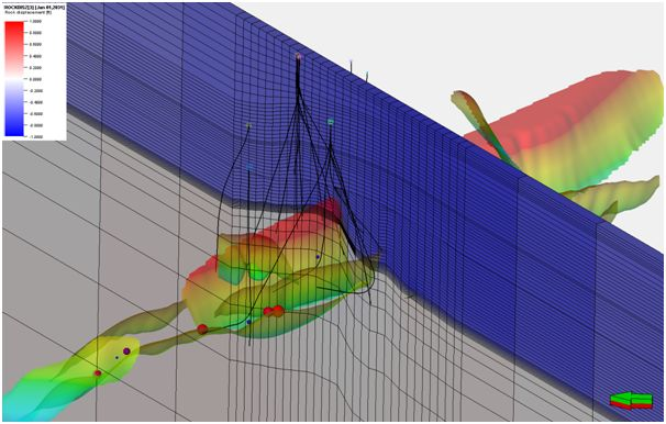
Vertical displacement (feet, blue is subsidence) above a gas reservoir at maximum depletion.
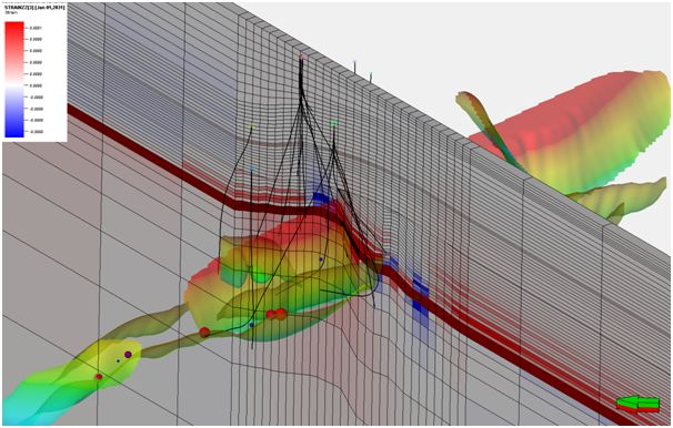
Elastic (recoverable) strain associated with maximum gas depletion. Red is compressive, blue is dilational.
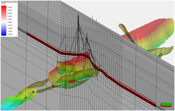
Plastic (permanent) strain associated with maximum gas depletion. Same scale and colour key as elastic strain picture. Note that most plastic strain is restricted to the reservoir interval (compaction).
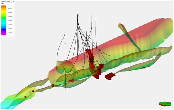
Fault related plastic shear strain (red = zero) and some fault related microseismic events within the reservoir interval at the time of maximum gas depletion.


